Location
University of Sheffield
Western Bank - Sheffield S10 2TN | United Kingdom
Fields of expertise
Urban flooding
Runoff pollution
Performance of urban assets
Digital water solution
Modality of Access
In-person
Access offered for each project
60 days
Number of Projects
1 (first call)
Expected composition of the visiting user-group
1 researcher during the full access period and 5 researchers for 10 days
Description
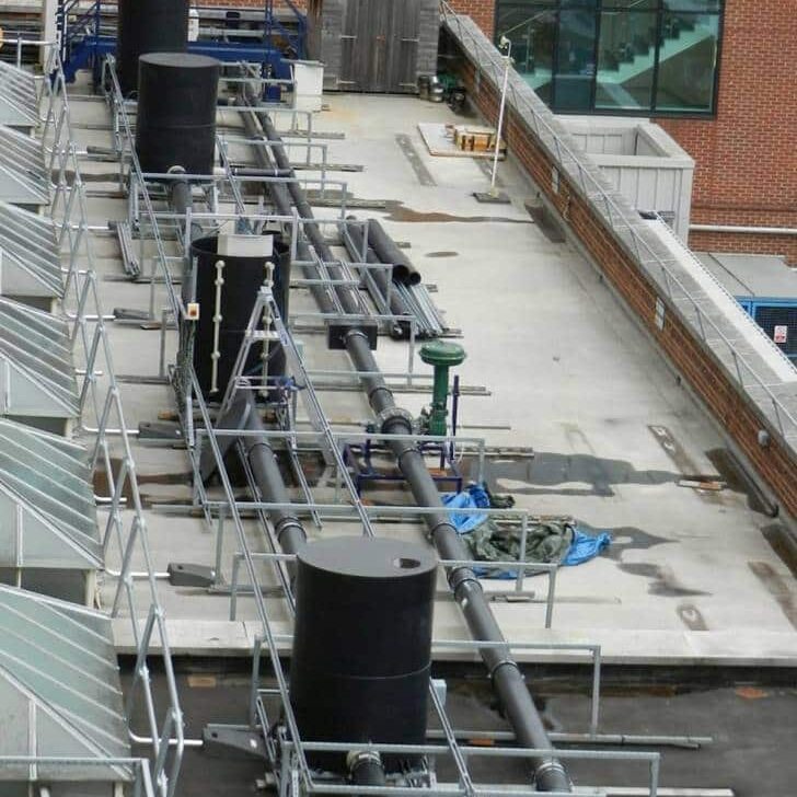
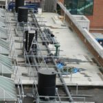
The laboratory facility consists of a 30 m long sewer pipe, 0.2 m in diameter with three manholes and a final CSO chamber 10 m downstream of the third manhole.
Each manhole is 1.5 m high and 1 m in diameter. The CSO chamber is 1.4 m by 0.5 m with a full width end weir. Water is pumped into the system by two submersible pumps capable of a combined output flow of 50 L/s, with the flow rate controlled by butterfly valves after each pump. A further butterfly valve, at the downstream end of the 0.2 m diameter “sewer” pipe, controls the water depth in the CSO chamber. CSO spills exit back to the main sump. Manhole 1 is fitted with a device to minimise any vortices/flow irregularities caused by the pump or upstream pipework. A weir in manhole 2, with 0.3 m crest width, was constructed 1.3 m above the manhole invert level to replicate additional upstream storage (i.e. represented as flow spilling over the weir).
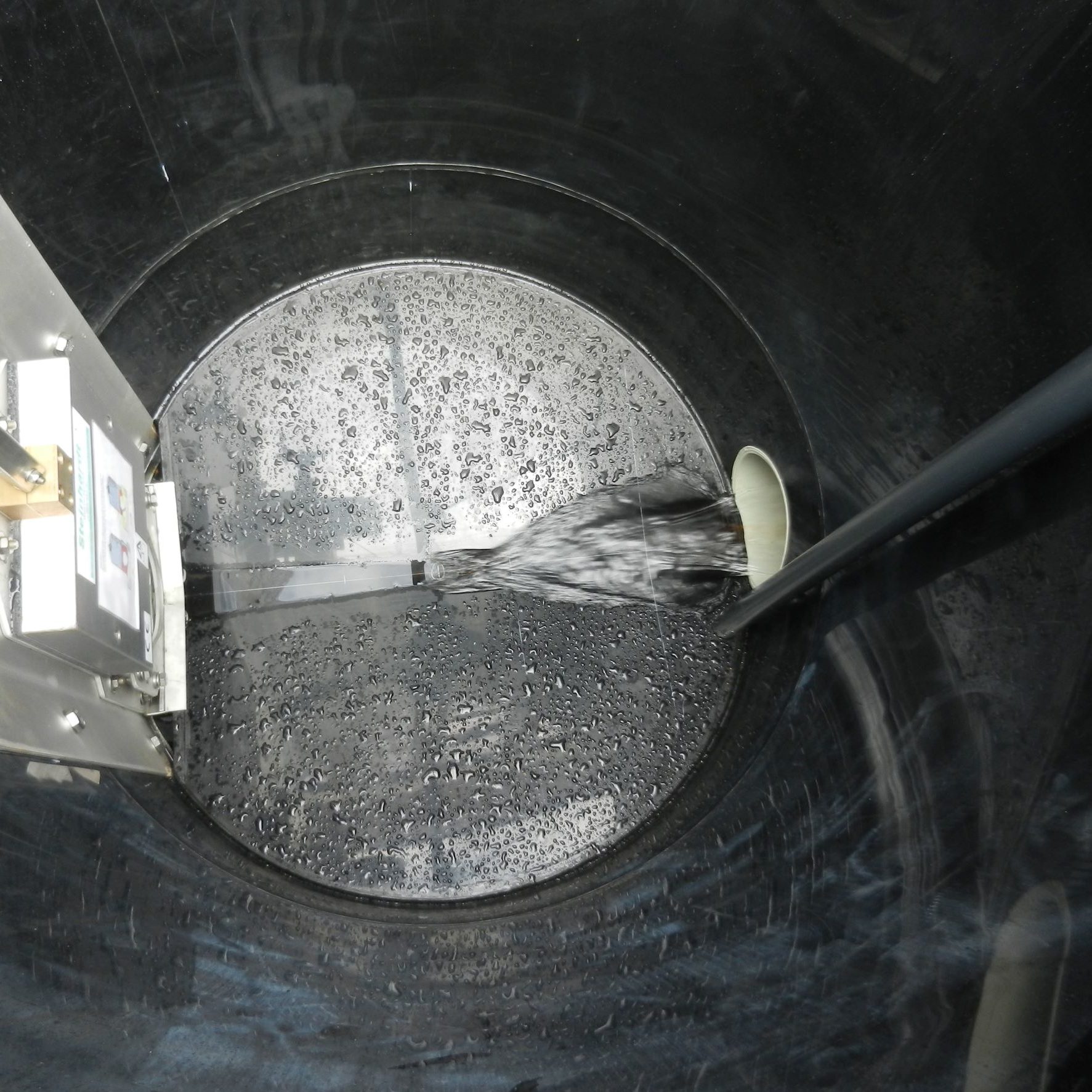
A flow control device (FCD) (Steinhardt HydroStyx Electric) with 0.2 m gate diameter is installed in the Manhole 3 and controlled by a Fuzzy Logic control algorithm. The gradient of the pipe is 1 in 500 to ensure adequate drainage. The facility includes two level monitoring sites (LMS) in manhole 3 (upstream of Gate) and one site in the CSO. Each LMS consists of a single pressure transducer which measured water level relative to the manhole invert level, at 0.1 Hz.
Service provision
The system has been extensively used to test hardware and control strategies for Real Time Control systems for urban drainage networks, originally for the EU H2020 CENTAUR project.
For example, the system can be used to test how different control strategies, sensing systems, and data strategies can affect the performance of RTC CSO spill mitigation techniques.
Users have included local SMEs and water companies, as well as a number of visiting researchers.
